Input conditions in. Drawings out in seconds.
We build systems that take your design inputs, run the full engineering math, and generate the 3D model — then release both proposal and production drawings, fully GD&T-annotated, while you're still on the call.
< 60s
Conditions → drawing set
2 stages
Proposal + production
GD&T
Applied automatically
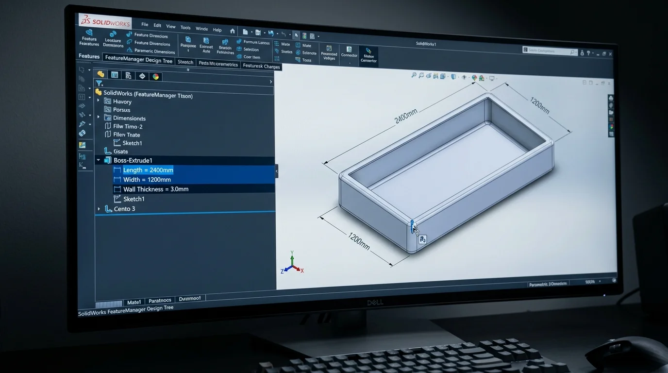
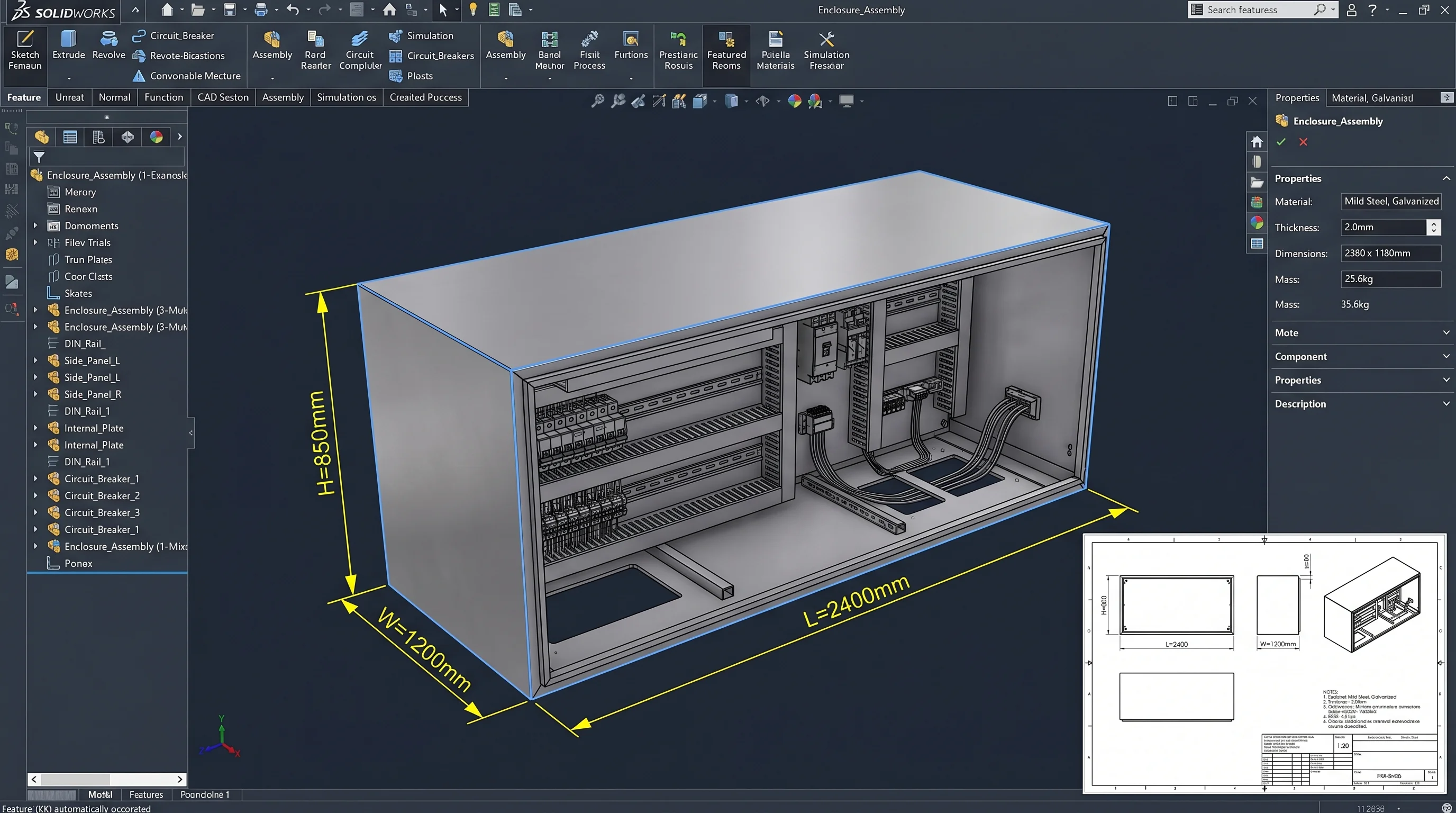
L: 2,400 mm
W: 1,200 mm
H: 850 mm
Length (mm)
2,400
Width (mm)
1,200
Height (mm)
850
Wall thickness
3.0
Material grade
IS 2062 E250
Surface finish
Powder coat
Mass
184 kg
Max σ
142 MPa
FoS
2.41
Defl.
0.9 mm
80%
Less proposal + production drafting
< 60s
Conditions to full drawing set
0 errors
Model, drawing, and GD&T stay in sync
3×
More RFQs quoted per engineer/week
One engine. From input conditions to released drawings.
We don't hand you a generic CAD plugin. We encode your design rules — the sizing formulae, the standards, the tolerances — so the same inputs always produce the same correct geometry and the same drawings.
Input conditions
What the part has to do
Engineering math
Your formulae, encoded
3D model
Associative parametric solid
Proposal drawing
For the quote · in seconds
Production drawing
For the floor · GD&T applied
It saves the drawing you make twice.
Every custom product gets drawn at least twice — once to win the order, once to build it. The system collapses both.
Quote with a real drawing, same day
When an enquiry lands, your team enters the conditions and gets a dimensioned GA drawing and indicative BOM in seconds — accurate enough to quote with confidence, fast enough to answer before a competitor does.
- GA drawing + indicative BOM per enquiry
- Costing-ready mass and material take-off
- Win-rate lift from same-day technical response
Release to the floor, GD&T right first time
Win the order and the same model drives the manufacturing set — fully dimensioned, datums and feature-control frames applied to your standard, title block and revisions populated. No re-drawing, no transcription drift.
- Full GD&T: datums, FCFs, tolerances to your standard
- Title block, revision table, and BOM auto-populated
- Model and drawing stay associative — zero mismatch
Tools built around your product geometry.
Parametric model generators
Input your dimensions, tolerances, and material specs into a configurator. Receive a fully dimensioned 3D model in STEP, IGES, or native format — in under a minute. No CAD operator needed.
- Drive geometry from spreadsheet or web form inputs
- STEP, IGES, SLDPRT, CATIA output formats
- Multi-variant family generation in one run
- Linked BOM auto-generation from model parameters
Generation workflow
Input parameters
Length, width, thickness, grade
Geometry engine
Parametric model computed
Output files
STEP + DWG + BOM generated
AutoCAD drawing automation
Eliminate manual GA drawing creation. Fully annotated drawings — views, sections, dimensions, title blocks, revision tables — generated from model parameters.
- Automated annotation and dimensioning
- Revision control and change tracking
- Batch drawing generation for product families
Product configurators
Customer-facing or internal configurators that let your team or clients define a product variant and receive a quotation-ready model and drawing set.
Legacy drawing migration
Convert paper drawings, scanned blueprints, or old DXF files into parameterised, editable 3D models with associated 2D drawing sets.
Built for your product family.
Every tool we build is specific to your geometry. These are examples from clients in similar industries.
Show us your partMachine tool builders
VMC and lathe beds sized to travel, spindle, and tonnage — generating castings, guideway layouts, and production drawings automatically.
Gear manufacturers
Spur, helical, and bevel sets driven by module, tooth count, and pressure angle — producing cutting data, inspection charts, and toleranced drawings.
Sheet metal fabricators
Enclosure families with variable height, width, and depth — each generating cut patterns, bend sequences, and GD&T drawings automatically.
Show us one part. We'll prototype the tool.
Send us a drawing or describe the product family. We'll scope a prototype configurator and show you the output within a week.